Sensors and ICs are an integral part of the car’s performance. They provide all the information necessary to control the transmission and inform future design choices.
Digital Sensors
Digital sensors represent data in a binary, high-low format. Digital sensors are used often because they “speak the same language” as computers and are noise resistant.
 1s are usually represented with the system’s nominal operating voltage (Vcc). Since we use a Teensy 4.1, this nominal voltage is 3.3V.
0s are represented with close to 0V.
CAUTION
Anything in the middle is known as the “grey zone” and can lead to unstable digital signals.
Pull-Up and Pull-Down Resistors
One of the first things to get comfortable with in electronics is that nothing behaves ideally. Ideally, if nothing is connected to a digital input, it should be an open circuit.
In the real world, digital inputs should always be at a well-defined voltage level, either Vcc or ground. If an input is left unconnected or “floating”, it can pick up electrical noise or stray signals in the air, leading to an unstable state.
To remedy this, we use pull-up and pull down resistors, which guarantee a state when the input isn’t connected.
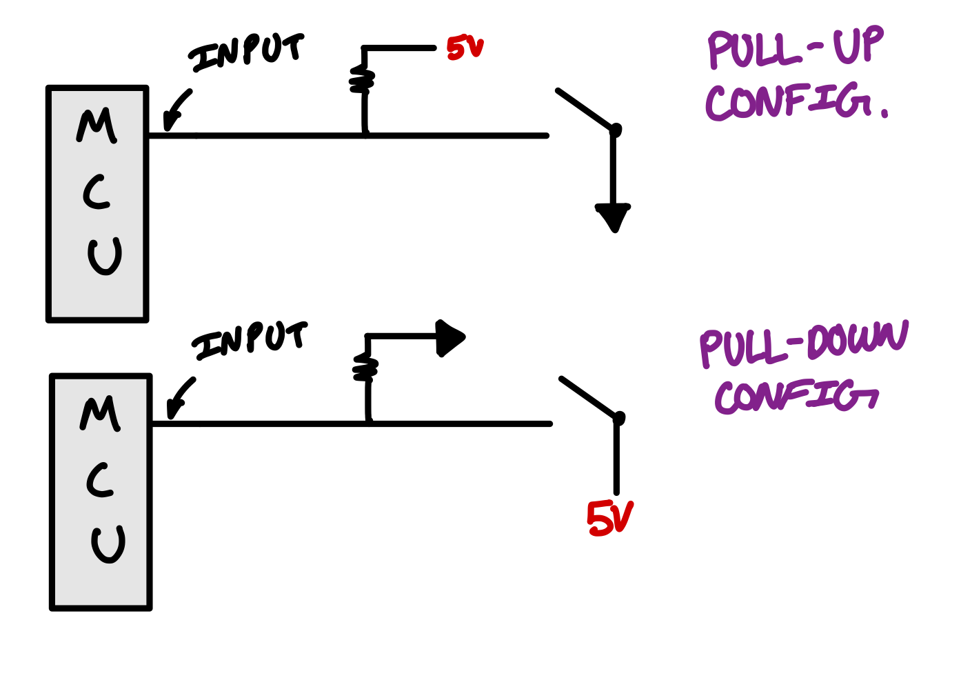
You can implement a pull-up resistor very simply by connecting a resistor from Vcc to the input pin. The smaller the resistor, the “stronger” the pull-up (more current can flow) and vice-versa.
You can implement a pull-down resistor by connecting a resistor from ground to the input pin.

Take some time to analyze the circuits above, considering the MCU as a very large resistor. You should be able to understand what the MCU reads when the switch is open and when the switch is closed. You should also be able to understand the effect of the pull-up and pull-down resistors.
The switch emulates a digital signal that’s left floating when not activated…
CAUTION
Be careful with conflicting pull-up and pull-down resistors, especially when dealing with level shifters. Some sensors may already have pull-up or pull-down resistors built in.
Level Shifting
Level shifting is the process of converting the upper threshold of a digital signal from one voltage to another.
One great example of where level shifting is used are the gear tooth sensors on M23. The gear tooth sensors return a logic high value of 5V, while the Teensy can only tolerate 3.3V. We can use a level shifter to shift the voltage of the signal to have a logic high of 3.3V.
The inner workings of a level shifter is well explained by this article from Digikey.
Analog Sensors
Analog sensors return a continuous signal that varies over time and can take any value within a given range. They are often used when you need to represent physical phenomena that are not discreet. They can be considered to have “infinite resolution”.
NOTE
Analog sensors are very sensitive to noise and EMI, so we often have to filter them.
Noise and Filtering
In any real-world system noise is an inevitability. Dealing with noise is a critical first step to any sensor processing, especially when it comes to analog signals.
I could write a whole section on just filtering, but I’ll leave that for the software knowledge transfer, since many of those algorithms are implemented in code. Instead, I’ll cover some high level basics.
When implementing any filtering scheme, you must consider the following things:
- How much information am I losing?
- How much phase lag can I tolerate?
- How much compute time does this take?