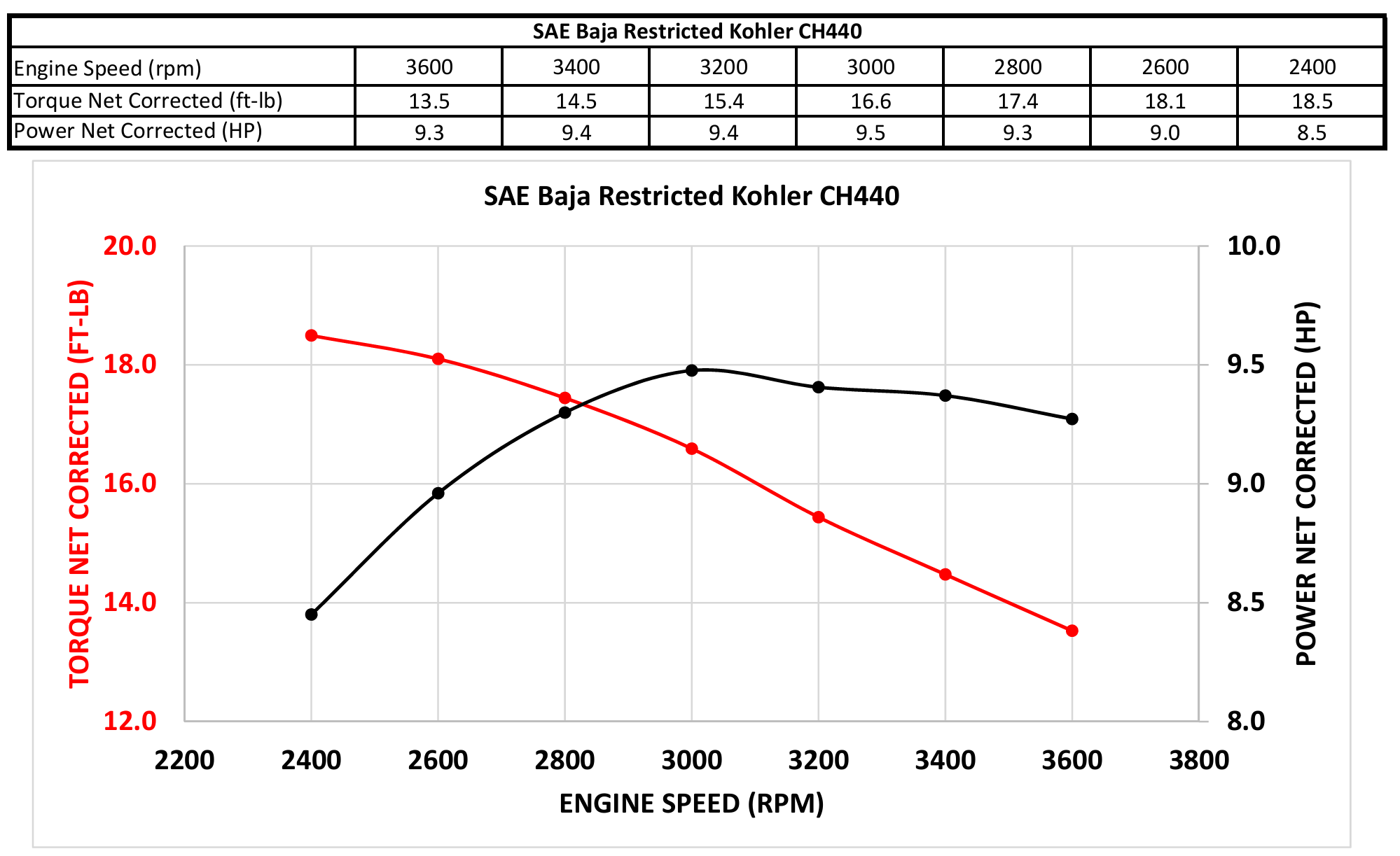
A controls system is the brains of the car, controlling the transmission to provide the optimal mix of torque and RPM at any given time. Internal combustion engines are limited to producing torque and power as per their torque-power curves. The torque power curve of the Kohler engine used on our Baja car is shown below:

NOTE
Notice how the power peaks at around 3000 RPM. In a naturally aspirated engine, the power usually increases consistently (more engine speed = more combustion cycles = more power!). The Baja Kohler engine uses a restrictor plate to choke the intake airflow. After the 3000 RPM point, the fuel-air ratio becomes too rich, reducing the amount of power output by the engine.
A transmission (in our case an ECVT) greatly improves the mix of torque and RPM that we can produce. With a transmission, we are theoretically only limited by the power output at any given RPM.
NOTE
Remember that and , where is torque and is power.
What’s Controls?
Controls gets its name from the field of control theory, which is the study of controlling the outputs of dynamic systems and machines. We use control theory to, you guessed it, control our car’s transmission ratio.
Why Controls?
Sure, we can control the transmission ratio…but what’s the ultimate goal? What are we trying to control in our system and what do we want that to look like?
The answer is a complicated question, and is still currently under investigation. The naïve answer is to just target the maximal power output by adjusting the transmission so that the engine is constantly outputting peak power.
However, nonidealities like wheel and belt slip, along with inconsistent running conditions mean that the fastest car is often one that targets a lower power in favor of more torque! The exact ratio is something we experiment with throughout the year and car vary from car to car.
How Does Controls Help?
Okay, so we can control exactly how much torque and RPM goes to the wheels and we want to provide the most used power possible. How does controls help with this? Let’s take a deeper dive.
No Transmission
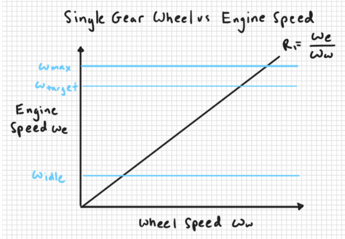
If we simply coupled the engine straight to the wheels and ran the car, you would get the following simplified graph:

There are a couple of problems with this. The engine is not running at optimal RPM except for a little bit. It’s really hard to start the car when you can’t control how much torque you have at the low end. Let’s explore a simple solution implemented in modern vehicles, the manual transmission.
In a manual transmission, we can control the transmission ratio to get a different looking graph.

When the transmission surpasses our target RPM, we can switch to a higher gear to put more load on the engine, slowing it down and maintaining our target RPM.
This graph looks a piecewise function, due to the fact that you usually only have around 6 defined gear ratios.
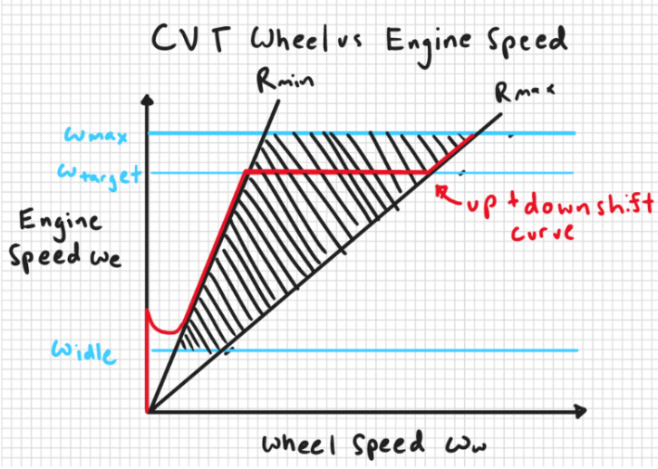
The graph of an ECVT on the other hand, looks a little something like this:
 We no longer have a single line for our output. Our transmission can take any number of paths to reach out target RPM and can be controlled to stay at our target RPM consistently.
By maximizing the time we spend at the target RPM, we can ensure that the car acts optimally and predictably! This is why we undertake the extra complication of building an ECVT.
The red curve is the idealized operation, but in practice, we see a lot more jitter and non-idealities.
Control Inputs
In order to control the ECVT, we’ll obviously need to keep track of the engine RPM. However, there are a lot of other sensor inputs that we utilize in order to improve the performance of our system further.
Engine Speed
The engine speed sensor returns the rotary speed of the engine in RPM. Read the article on gear tooth sensors to learn more details. You can also refer to this implementation guide for more information!
Since the engine speed sensor measures the RPM closest to the actuator, it is most tightly coupled with the primary sheave and controls system. In general, the engine speed sensor controls the short-term transients of the controls system.
I highly recommend reading the ECVT description if the mechanical aspects are confusing.
Wheel Speed
The wheel speed sensor measures the rotary speed of the gearbox at the input shaft. By assuming that there is no speed loss from the input gear to the wheels of the car, we can calculate the rotary speed of the car’s wheels!
Since the wheel speed sensor measures the gearbox, which is directly coupled to the wheels, we use the wheel speed sensor to inform the controls system about the long term behavior of the car. For example, the wheel speed sensor can tell us if the car is at a standstill, or if it’s moving at top speed!
Throttle and Brake Inputs
The throttle and brake sensor tell us how much the throttle and brake of the car are pushed. They allow the driver to directly influence the controller with their pedal inputs.
Because there is some lag between using the pedals and accelerating/braking (this lag is inherent in the system), throttle and brake inputs allows the controller to “predict” the behavior of the car.
For example, if the driver were to rapidly push the throttle pedal all the way down, we would expect the RPM of the engine to rise after a short delay. The throttle sensor would allow the controller to “expect” the RPM to increase before it actually does!
Controller Details
Our basic controller is a PID controller with feed-forward elements. For the sake of competitiveness, I will not divulge details of our controller, and all discussion will be kept general.
Feedback Control (PID)
Feedback control systems are commonly used to control complex processes. We make use of a PID controls system to control the transmission. The complexity of controller that we can use is limited by the complex physical properties and non-idealities of an ECVT, which make it hard to model.
 The block diagram above illustrates the basic controller we use. When tuning the car, we modify the parameters inside the PID block. We can also control the reference signal, , in order to achieve the desired engine RPM curve. The real life output of the system is the . I’ve chosen to ignore sensor noise for the sake of simplicity, but you must not do so in real life!
The PID block takes our reference signal and “converts” it to a command to the actuator. This results in a change in RPM, which the PID controller reads. This process happens 100 times a second, controlling the RPM to be as close to as possible.
Feed Forward Inputs
A feed forward input is an input that quite literally feeds forward into a later section of the block diagram. Feed forward inputs are useful when you want a signal to directly impact a later section of a block diagram.
Results
Ultimately, this controls system gave much stronger performance than in previous years. The transmission effectively prevents the car from stalling, which was a large problem in previous years. It also is quite snappy in the low range. A picture of the transmission’s tracking from the Pennsylvania competition is shown below.
As you can see, the tracking performance is not bad, and the system generally follows the target reference signal!
Improvements
The graph above also highlights significant improvements to be made to the controls system. While the controller generally tracks the reference, we can observe significant overshoot and poor tracking, especially at the higher RPM ranges.
Furthermore, the large downwards crash in RPM at the beginning of the graph is indicative of a large lurch on initial acceleration. This lurch, and consequent crash in RPM significantly limits initial acceleration.
Tracking on Braking
Due to a lack of quality in brake data, we are not able to fully characterize the vehicle during deacceleration. This causes poor tracking. In future iterations, the brake measurement system should be based on the pressure in the brake line, with the brake used as an essential sensor input.
Response Time
Multiple drivers have complained about the lack of responsiveness when they press the throttle. This is indicative of an overdamped controller, as well as a consequence of the actuator taking time to engage the belt with the sheaves.
You can solve this problem by tuning the controller to be more responsive, and implementing engage position control, where the actuator holds the belt right at the edge of engagement.
Tuning Process
We can also significantly improve the tuning process for the vehicle. Presently, we tune the car by analyzing the tracking performance and changing the PID parameters off feel. This is a terrible way to tune a controller.
To improve this process, we should turn to empirically based tuning processes, considering the fact that we don’t have a model. A great example of this is the Zeigler-Nichols method, which is an empirical way to tune PID controllers.