 Hi! My name is Rama, and I was the controls hardware PE for UCLA Baja SAE during the years of 2023-2024.
Baja is a student-led off-roading competition where students design, build, and race an off-roading car throughout the school year. Baja cars are tested on their rock crawl, hill climb, acceleration, endurance, and more!
It’s the job of the controls hardware PE to design the electrical framework for the ECVT (Electronic Continuously Variable Transmission) and to provide the infrastructure to collect data to inform future design decisions.
I’m building this guide as an open source knowledge transfer document, with the intention of sharing what I’ve learned over the year in PCB design, harnessing, sensor selection and processing, control theory, and power.
Overview
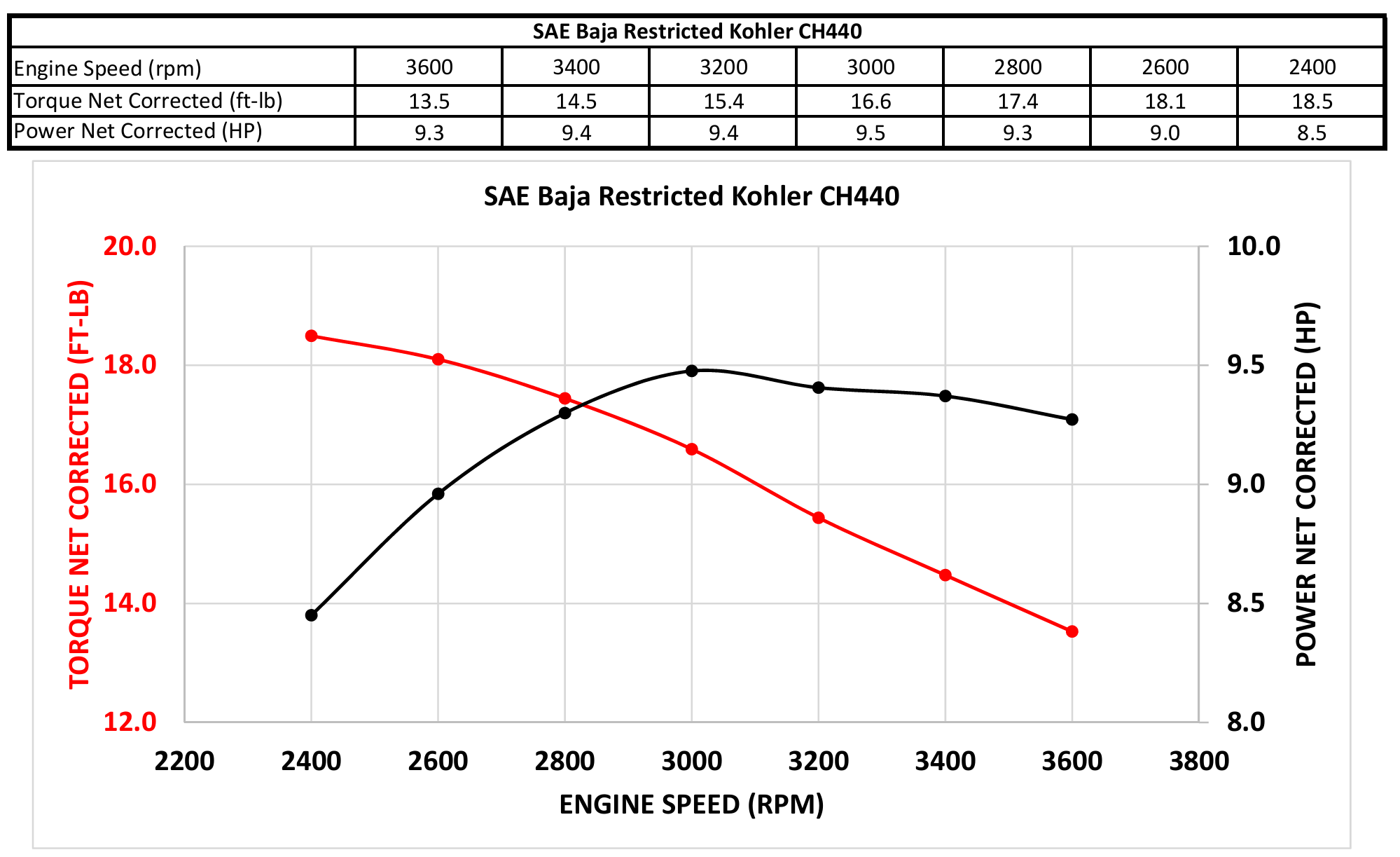
M23’s powertrain ran on a 10HP Kohler engine with a peak low-end torque output of around 18 ft-lbs.
 CH440 dyno charts from Kohler
In order to perform well, the car needs to have a highly adaptable mix of torque and RPM. RPM is useful on long, unimpeded straights, while torque is particularly useful in difficult terrain or for obstacles. The exact mix of the two can heavily depend on track conditions, which necessitates the development of a highly adaptable transmission.
To respond to this need, we’ve created the ECVT, an electronically controlled variation on a traditional CVT transmission. An ECVT’s main advantage over a traditional gauged CVT is that it can be finely adjusted and tuned with a simple code push. This adaptability means that we can quickly change tuning based on track conditions or event.
Click here to learn about the mechanical workings of an ECVT
NOTE
For software questions, contact Grant Paulker. I should also be able to answer high level programming questions that don’t go too far into the weeds.
Objectives and Goals
Baja is ultimately an endurance competition that tests the performance of an off-roading car over multiple different events (acceleration, suspension, etc.). Our goal on electronics is not only to control the car’s transmission, but also to provide data to other subteams to inform future design decisions.
Here’s a quick summary of our design goals and improvements for M23:
- Provide clean, robust data for the controls system to have > 95% uptime.
- Eliminate stalling issues present in M22
- Implement proper system compartmentalization to protect critical subsystems in the event of a subsystem failure.
- Design a simple tuning process.
- Anticipate future modifications to the electronic system.
Hardware Overview
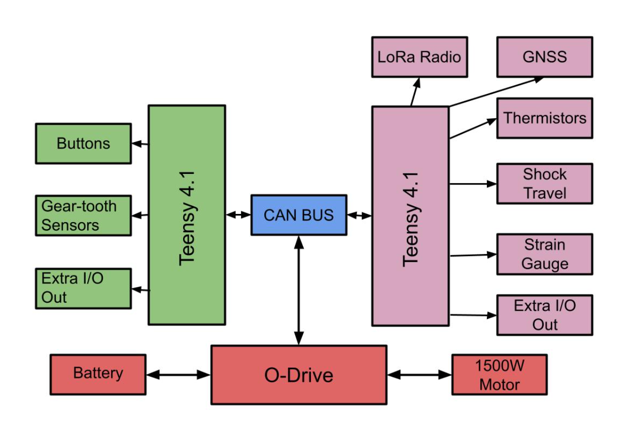
 The electronics system diagram for M23
The green Teensy 4.1 on the left is part of the M23 Main PCB. The lavender Teensy 4.1 is part of the M23 DAQ PCB. Not pictured in this diagram is the M23 Dashboard PCB.
At the core of the system is the main PCB (green). The main PCB is the brains of the car. It takes in the engine RPM, wheel speed, and pedal positions and feeds that into a controls system to decide how fast and in which direction to shift the transmission.
The DAQ PCB can be thought of as the secretary of the car, logging all the data points on the car for later review.
In one endurance race last year, we logged 30 million data points!
The red system at the bottom is our power and actuation system. A 52V E-bike battery feeds power to an O-Drive Pro motor controller. The O-Drive allows us to send simple velocity or position commands to the BLDC motor controlling the ECVT and also provides regenerative braking functionality.
The blue CAN BUS is the information highway that facilitates communication between all three of these systems.
Contents
- Basic Operation
- PCB Design
- General Guidelines (WIP)
- DAQ PCB (WIP)
- Main PCB (WIP)
- Dashboard PCB (WIP)
- Harnessing
- Sensors and ICs
- Power System (WIP)
- Actuator and Actuation (WIP)
- BLDC Motors (WIP)
- O-Drive Pro (WIP)
- Battery and Power Distribution (WIP)
- Actuator and Actuation (WIP)
- Control Theory
- Instrumentation
- Known Issues and Troubleshooting (WIP)
- Further Improvements (WIP)
Acknowledgements
I’d like to thank the following people, who were instrumental in providing me guidance and support through the whole process of designing M23’s electronics system:
- Arnav Doshi
- Drew Gautier
- Prasanna Srinivas
- Getty George
- Grant Paulker
- Paige Larson
- Beni Korol
I couldn’t have made any of this happen without the people above.
Contact Rama: adi.k394@yahoo.com