Geometric optics bend and shape light through the use of reflective and refractive elements (read The Nature of Light to learn more about the fundamental principles behind how these work). Below are some common optical elements and their properties and effects on images.
Plane Mirrors
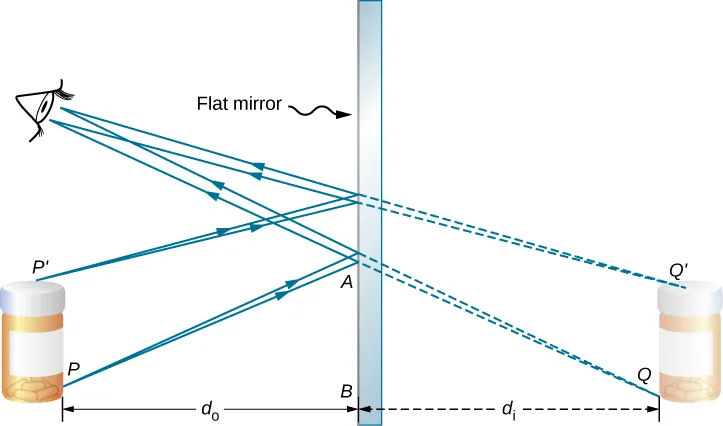 In the above example of a plane mirror, light reflects off the mirror and goes to the observer’s eyes. Interestingly, while the object is right under the observer, the image that you see through the mirror seems to be coming from within the mirror.
Such an image is called a virtual image because it cannot be projected onto a screen. If you walk behind the mirror the image will not exist. In contrast, some optical elements create real images, which can be projected onto a screen!
A plane mirror has an interesting property where
The distance from the mirror to the object () is equal and opposite to the distance from the mirror to the image (). Using this fact, we can reconstruct an object from an image and vice versa by applying this to every single point on the object.
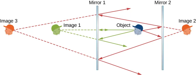 Objects can also reflect more than once to create multiple images!
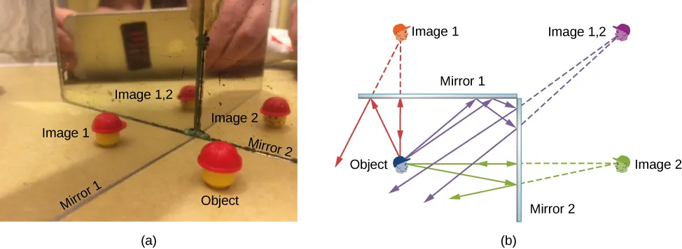 The expression for the number of images n formed due to two plane mirrors inclined at an angle is
Curved Mirrors
Curved mirrors differ from planar mirrors in that they can distort and displace objects in more ways than the single dimension that a planar mirror can. We will focus on two kinds of mirrors:
- Concave: Forms a cave for the light (inner radius reflective).
- Convex: Looks like a shield against the light (outer radius reflective).
The Focal Point for a Curved Mirror
The symmetric axis of a curved mirror is called the optical axis. On this optical axis lie
-
Focal point: Where all the incoming light rays converge.
-
Vertex: The point where the optical axis and the lens intersect.
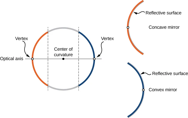 With these two definitions, we can define a critical quantity, called the focal length. The focal length is the distance from the vertex to the focal point!
NOTE: The focal point can occur behind or in front of the mirror! Thus, it’s very critical to use the PROJECTION of the reflected rays to determine where they converge (the projection means you continue the line in both directions to infty).
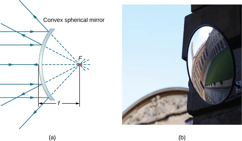 For a curved mirror the focal length is simply:
NOTE: In the derivation of this formula, the small angle approximation was used. This means that this formula holds valid for curved mirrors where the distance that rays travel is much smaller than the curvature of the mirror.
Geometric Ray Tracing for Curved Mirrors:
Ray tracing is a technique that we can use to determine the position of an image after an object’s interaction with a mirror.
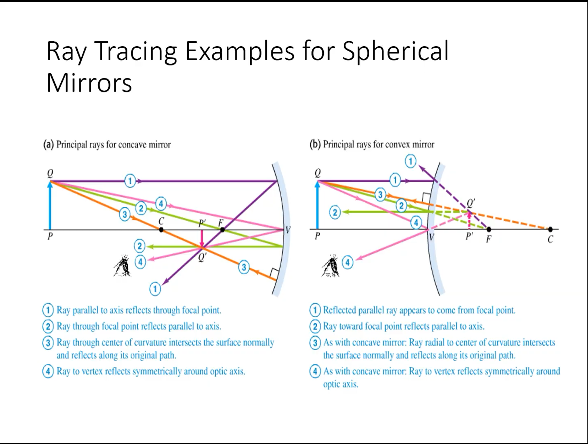
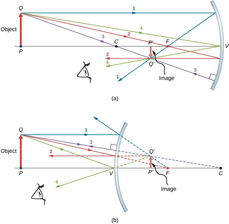 In the two images above, there are 4 principle rays that must be analyzed to determine where an image is. These rays are as follows:
- P-ray: Parallel ray; comes in parallel to the optical axis.
- F-ray: Focal ray; proceeds from/towards focal point and becomes parallel to the optical axis.
- V-ray: Vertex ray; incident on vertex of mirror/lens, reflects off at the same angle from which it came (symmetry about the optical axis).
- C-ray: Center-of-curvature ray; proceeds from/towards center of curvature. This ray reflects back from where it came!
Critical Equations for Curved Mirrors:
The mirror equation is given by: where is the distance of the object image, is the image distance and is the focal length.
NOTE: The focal length is positive for concave mirrors, and negative for convex mirrors! The image distance is positive for real images and negative for virtual images!
Another form of this equation is: Where n is the index of refraction of the materials and R is the radius of curvature. We can also solve for the magnification where is the image height, is the object height, and m is the magnification. If , the image is enlarged. If , the image is shrunk. If , the image is inverted. If , the image is upright.
Sign conventions in optics can be tricky and important, so here is a helpful graphic:
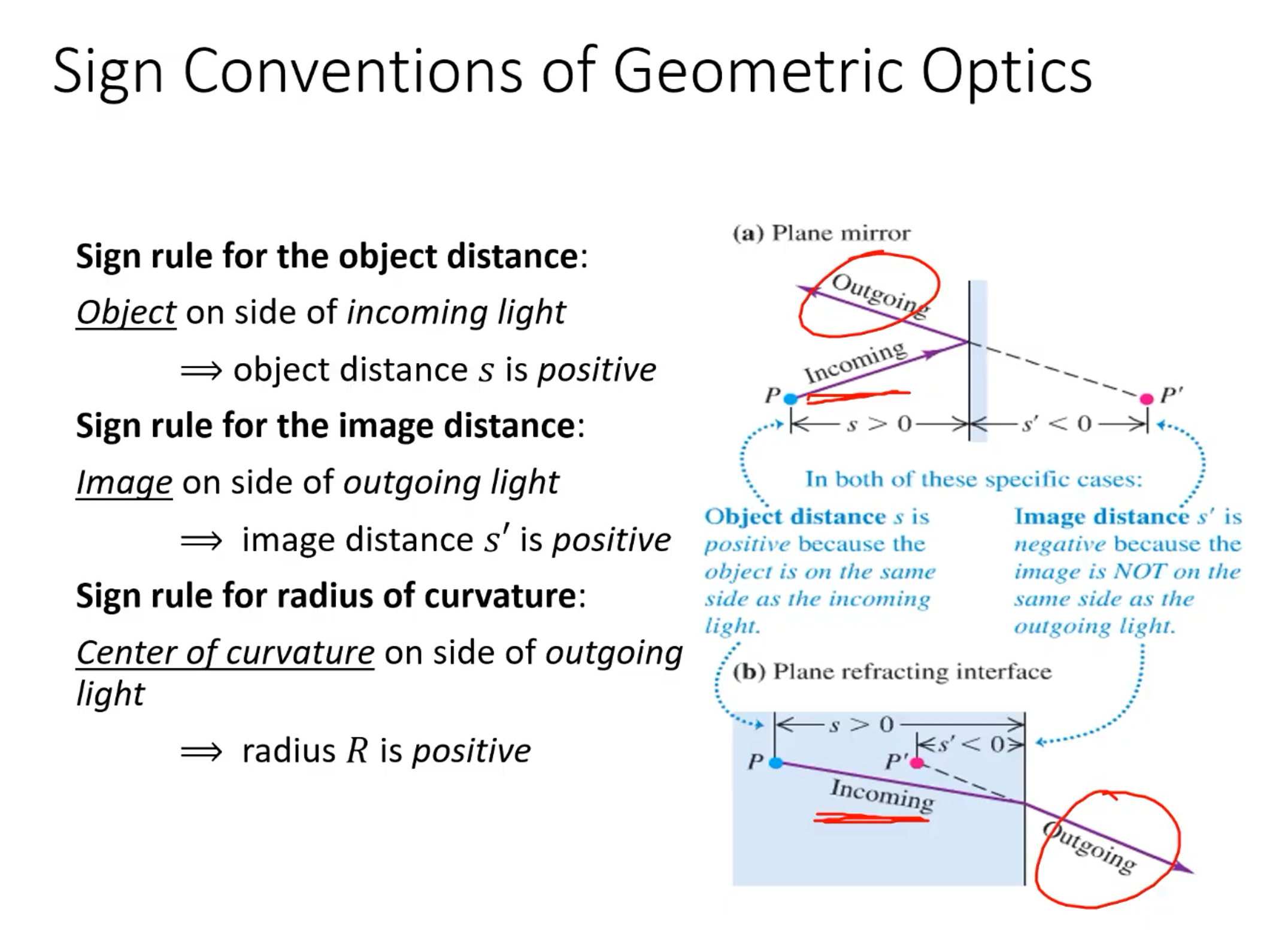 ^ THESE ARE VERY IMPORTANT
Images formed by Refraction:
Often times in real life (most notably when looking into water), we encounter images that are distorted and shifted by refraction. Such an example is presented below:
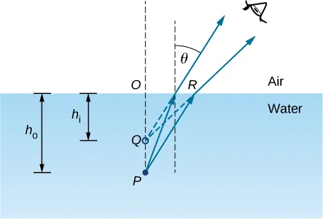 Consider the rays from the point P, when they get refracted and reach our eyes, the refracted rays make it seem as if the object is at point Q! The depth that we “see” is called the apparent depth: (the height of the image). The actual depth of point p is the object height . We can use the small angle approximation for a “normal viewing angle” and derive the following formula:
Thin Lenses
Lenses are perhaps the most useful/most used optical devices in instrumentation today! There are two main classes of lenses:
-
Convex or Converging: All light rays that enter it parallel to the optical axis intersect or focus at a single point on the optical axis on the opposite side of the lens.
-
Concave or Diverging: All rays that enter parallel to the optical axis diverge from the focal point.

NOTE: A lens is considered to be “thin” if the thickness is much less than the radii of the curvature of both surfaces. This allows us to assume that the light rays are bent only once at the center of the lens.
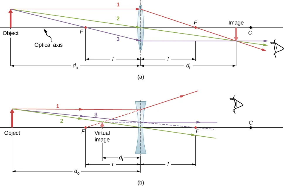
 Converging lenses have positive focal lengths. They take parallel rays of light and converge them onto a single point. This point where they converge, this point is called ! The point where they are diverging is called .
 Diverging lenses have negative focal lengths. They take parallel rays of light and diverge them from the focal point. This point where they converge, this point is called ! The point where they are diverging is called .
NOTE: The locations of F2 and F1 are flipped from the convention for converging lenses. This is to keep with the convention that F1 is the place where they are diverging and F2 is the place where they are converging.
Ray Tracing Rules for Thin Lenses:
The ray tracing rules are different for thin lenses than they are for curved mirrors!
- P-ray: Starts parallel to the optical axis and goes through the focal point after the lens.
- V-ray: Goes through the center of the lens and does not deviate from its course.
- F-ray: Goes towards to begin and ends up parallel to the optical axis after lens.
Oblique Parallel Rays and The Focal Plane:
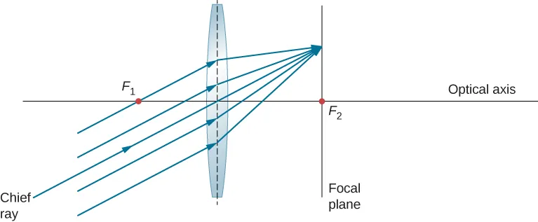 If the rays incoming are not parallel to the optical axis, they do not converge at the focal point, but instead on the focal plane, which is perpendicular to the optical axis and intersects the focal point (shown above).
Thin Lens Equations:
Thin lens equations are surprisingly similar to those for curved mirrors, but differ in a few key areas! For a thin lens: We can also take this further to find a special equation called the lens maker’s equation, which is defined as follows:
The magnification is as follows:
- If , then the image has the same vertical orientation as the object (called an “upright” image).
- If , then the image has the opposite vertical orientation as the object (called an “inverted” image).
Sign Conventions for Thin-Lens Equations:
- is positive if the image is on the side opposite the object (real image); otherwise, is negative (virtual image).
- is positive and real if the light rays come from the object side. is negative and virtual if the light rays don’t come from the object’s side.
- is positive for a converging lens and negative for a diverging lens.
- is positive for a surface convex toward the object, and negative for a surface concave toward object.
- is positive for upright (virtual images) and negative for inverted (real images).