While previously, our simplification of light as a ray worked for Geometric Optics and The Nature of Light, it lacks the power/intensity of light and additional relevant information. Wave optics corrects this lack of information, by making our interpretation more complex.
Viewing Light as a Scalar Light Wave
We now view light as a scalar light wave, with the light ray as the center of oscillation.
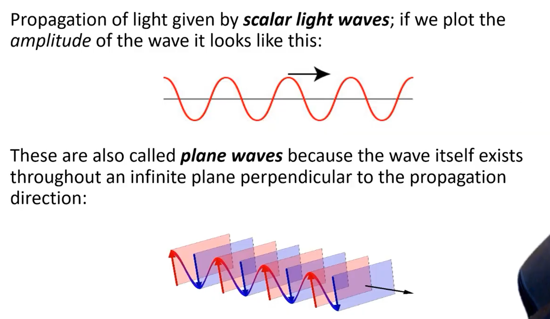
Light as a wave has a speed, wavelength, and frequency! However, we learned in The Nature of Light that light can have different speeds depending on the material that it passes through. If the speed of a wave is , what must change: the wavelength or the frequency?
The answer is that the wavelength changes! The new wavelength is the wavelength in vacuum divided by the index of refraction.
NOTE: Do remember that the index of refraction changes slightly based on the frequency (color) of incident light!
Light as a wave can also have a phase! For a propagating wave: Furthermore, two superimposing waves with different phases will interfere. There are three contributions to the relative phases between waves: The three possible sources of phase difference are summarized in the equation above, and are talked about more further below
Initial Condition Phase Difference
The initial condition phase difference occurs when two waves begin out of phase! This source of phase difference is all about the in the equation above that offsets the wave!
Path Phase Difference
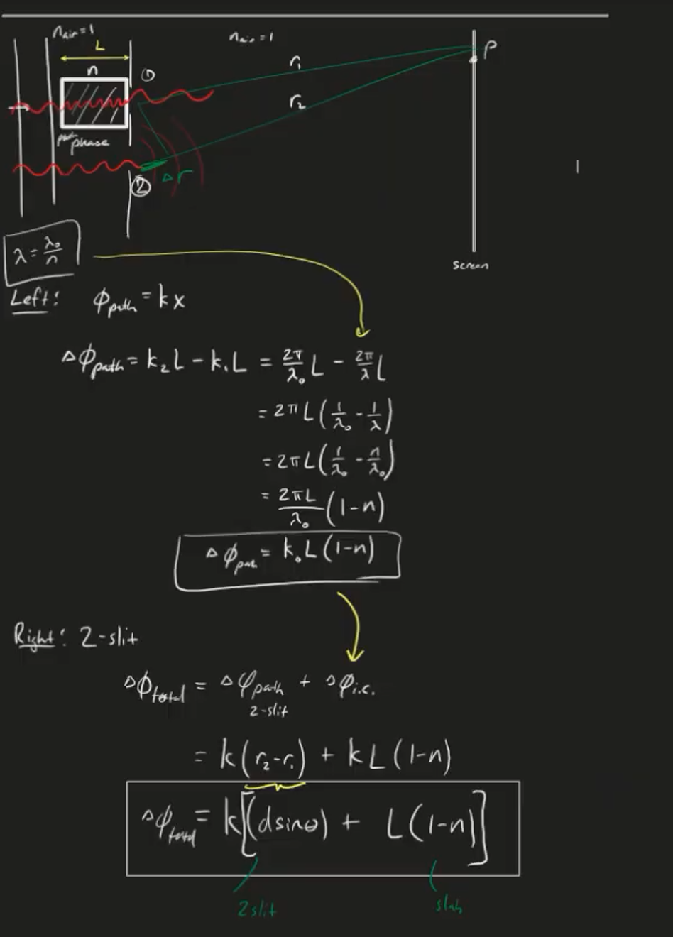
The path phase difference depends on the difference in the path taken. When two waves travel different paths and to point P, there is a relative path phase difference given by: For two waves sources that are in phase, constructive interference occurs at: and destructive interference occurs at:
Two Source Interference Pattern
The two source interference pattern occurs when two point sources interfere with each other.
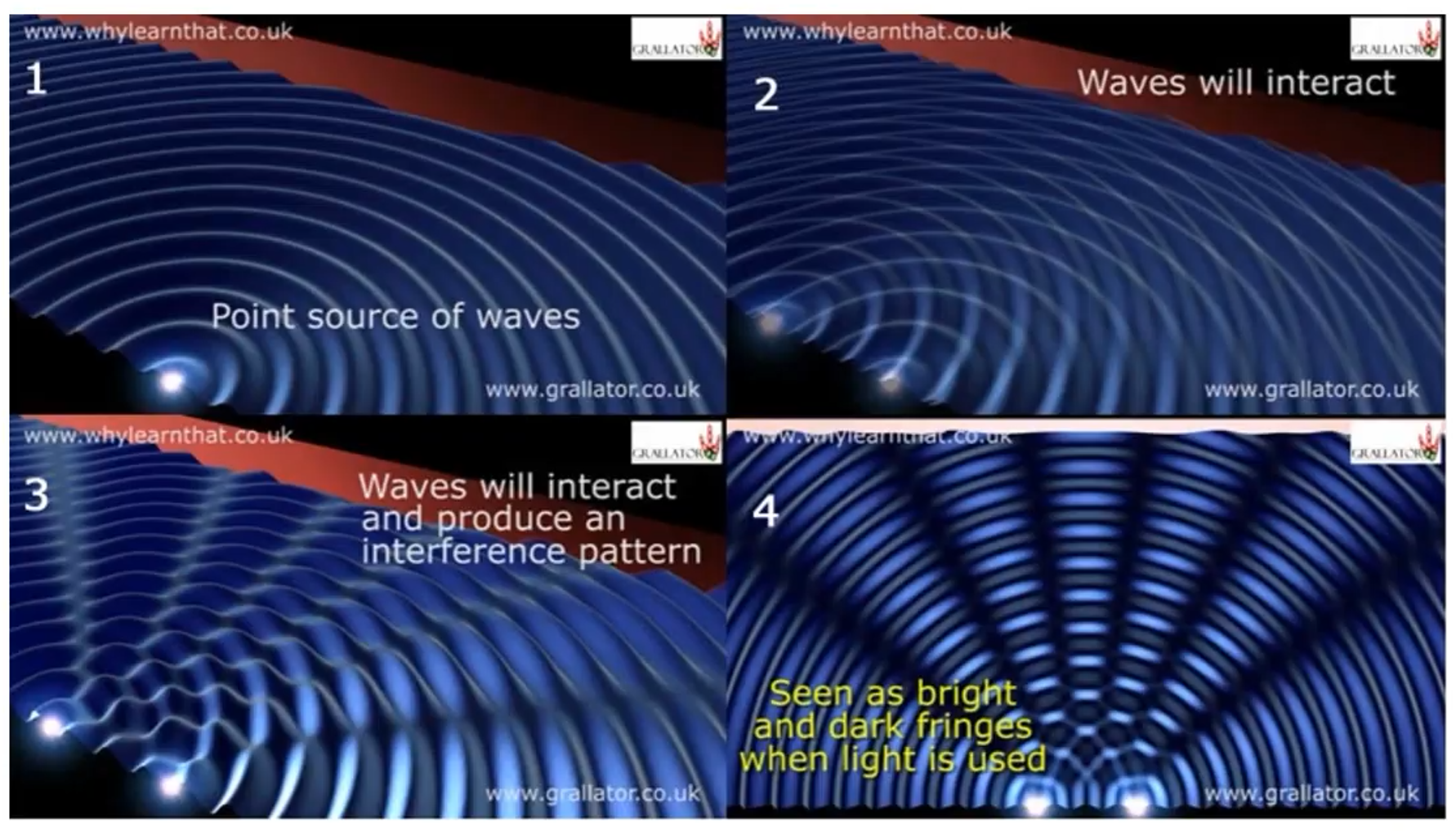 In image three above, the raised “hills” are the locations for constructive interference. The “valleys” are regions of destructive interference.
Example:
Young’s Double Slit Experiment
The Young Double Slit experiment cemented the idea that light was a wave. If light was a particle, then in the image below, you would only see two lines directly across from the double slit.
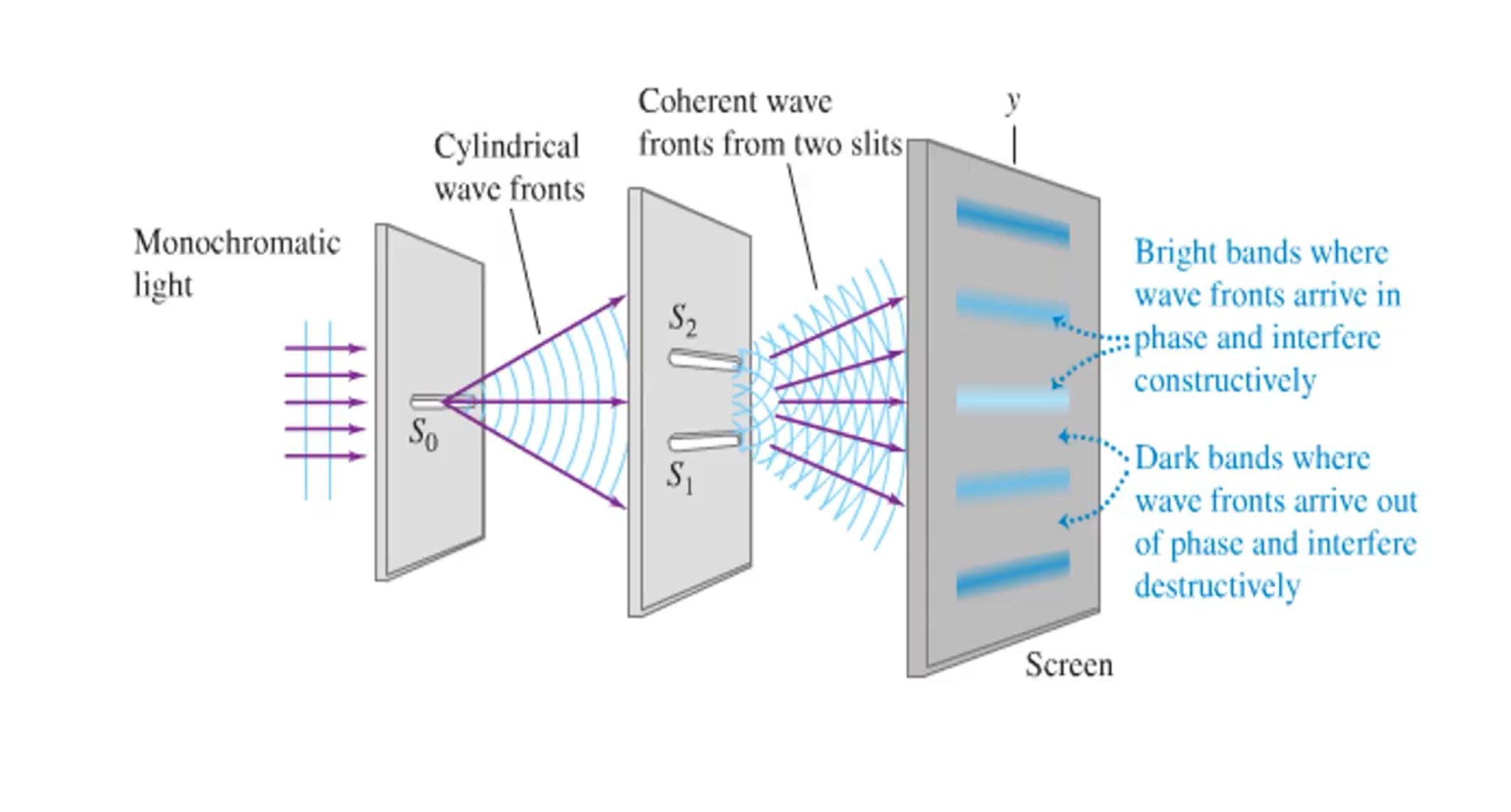 With our wave model of light, we can now see why the image above occurs. But first we must make the important assumption that the size of the slit is much, much smaller than the distance to the screen!
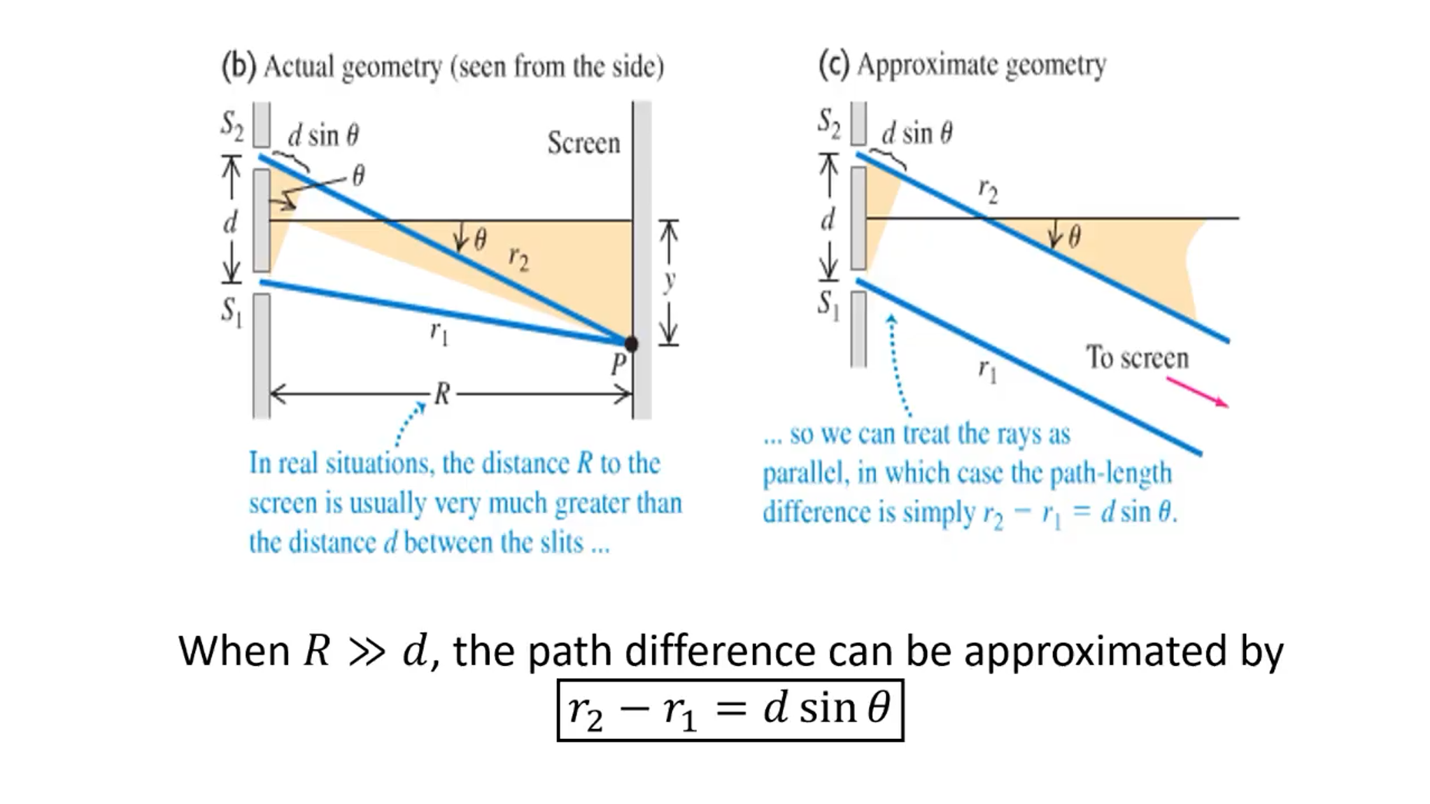
Constructive interference will be at locations: or where ).
Destructive interference (dark spots) will be at locations: or where ).
We can also characterize the light spots and dark spots in terms of the height: For the bright spots: For the dark spots:
NOTE: n represents the ORDER of the interference, and y represents the distance from the centra maximum to the nth bright fringe! R represents the distance from the slit to the screen.