Gear tooth sensors are primarily used to detect the angular velocity of a rotating object. We use them in our system to monitor the RPM of the engine and the wheels, two critical components of our controls system. If you’d like to view a working example of using a gear tooth sensor, please refer to this guide.
Working Principle
A gear tooth sensor module consists of three main parts:
- A permanent magnet to provide a magnetic field
- A hall effect sensor to detect changes in the magnetic field
- A gear or reading disk with teeth made of a ferromagnetic material
IMPORTANT
Whatever the sensor reads MUST be a ferrous material
The permanent magnet inside the gear tooth sensor creates a magnetic field which can be read by the hall effect sensor.
When the reading disk or gear rotates each tooth and valley pass by the sensor. The ferromagnetic material entering and leaving the magnetic field causes disturbances in the magnetic flux.
If you’d like to understand the working principle behind this phenomenon, read about eddy currents
The hall effect sensor detects the change in magnetic field. When a gear tooth approaches the sensor, the flux increases, and when the tooth moves away, the flux decreases.
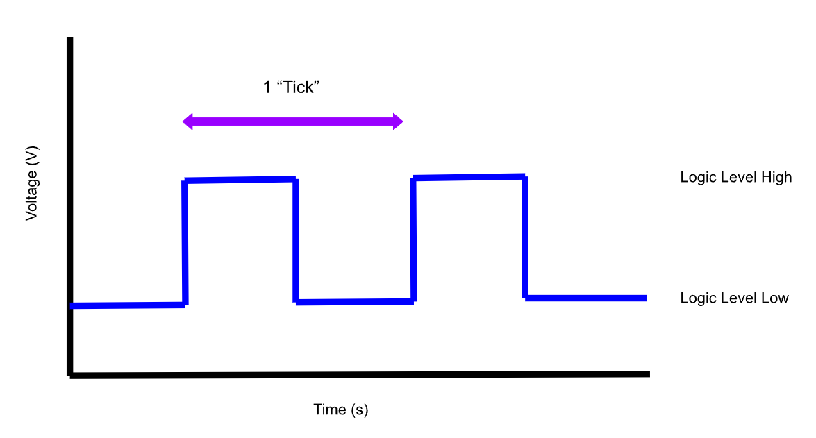
The gear tooth sensor converts the magnetic field changes into an electrical signal, which in our application is usually a square wave. Each pulse of the square wave corresponds to the passing of a gear tooth or slot in the reading disk.
We call each pulse on the output wire a “tick”
 Illustration of a single “tick”, as if you were reading the output line with an oscilloscope.
To achieve reliable ticks, it’s critical to follow the manufacturer specification on the distance between the reading face of the gear tooth sensor and the thing being read.
NOTE
Incorrect air gaps can lead to unstable signals. Usually gear tooth sensors rely on comparator or transistor logic internally. Having a weak change in magnetic flux can cause the outputs to “jiggle”. If too few or too many ticks are being read, this could be a cause.
Current Implementation
In previous years, we made our own gear tooth sensor modules with a MLX90217LUA gear tooth sensor and 8019 radial magnet. This approach proved to be easy to package, but unreliable and prone to heat failure, especially since it was housed inside the ECVT cover.
This year, we began using industrial gear tooth sensors, which are packaged in environmentally protected metal threaded bodies. This allows us to securely mount the gear tooth sensors in high temperature environments without worrying about them failing.
We used two SKUs from Digikey, the A44-18ADSO-P5P21 from Standex-Meder and the 55075 from Littelfuse.
NOTE
Both of these sensors output a 5V signal and take a 5V supply. Thus, you will need a level shifter to convert the signal to 3.3V for the Teensy.
We used this level shifter module from Adafruit that’s rated for I2C communication, but you could also move to a custom MOSFET implementation if you’re comfortable.
Engine RPM Sensor
Due to packaging constraints in the transmission, the Standex-Meder was chosen to read the engine RPM for its small size. It was very expensive at 25 for the Littelfuse).
CAUTION
These sensors have a built in 5k pull down resistor, which can interfere with pull up resistors found on some level shifters! We learned that the hard way after 6 hours…
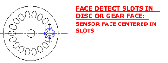
In our implementation, the sensor reads a reading disk attached to the engine output shaft. This reading disk has 16 slots. The sensor is triggered when it passes these slots.

The rationale for using 16 slots is explained in the Fourier Analysis Section.
Secondary RPM Sensor
The secondary RPM sensor utilizes the LittleFuse sensor and was mounted in the gearbox parallel to the input gear’s face. This meant it was reading a much smaller change in flux, and as a result had to be placed 1mm from the face of the gear in the gearbox.

TIP
Instead of what’s shown above, I highly recommend that you place the gear tooth sensor inside the gearbox such that it radially reads the gear. This gives the sensor more margin and better performance.
Fourier Analysis
A critical design consideration is how many “ticks” per rotation to have for each sensor. This was a heavily thought through decision for the primary gear tooth sensor. On one hand, having too few ticks would provide too poor a resolution for the control cycle to effectively control the car. On the other hand, adding too many ticks would make the reading disk weak, leading to deflection during normal operation which could break the gear tooth sensor. Thus, it became necessary to figure out the minimum number of ticks required per rotation.
To determine the minimum number of ticks required, we had the car run a max braking test, and then we took the Fourier transform of the RPM data. This gave us some really nasty units (Revolutions vs power), but was still sufficient enough for us to determine (using the Nyquist principle), that we needed 16 ticks per revolution!
TIP
Ideally next year, we spec the disc with FEA, putting the max number of ticks on there until it deflects enough to make us worried. This is because with a small number of ticks, the resolution suffers while idling and at low speeds. By adding more ticks and getting more resolution, we improve the responsiveness of the car as well.
